Mini Cooper Power Steering Pump Fuse
"Which fuse is for the elecronic power steering pump on a , Power Steering Pump Fuse North American Motoring, Alternator and power steering dead related North , MINI Cooper S 2005 Fuse Box Block Circuit Breaker Diagram , COMFORT CONTROL MODULE MINI COOPER , Mini Cooper Relay R1 Factory Replacement R50 r61, Ignition Switch - Circuit Wiring Diagrams, F S 2006 Mini Cooper S Ready for Race Show MBWorld , 1968 Mk2 Mini Cooper Woodcote Racing Classics, Front Bonnet MINI COOPER R53 R52 R50 Gen 2006 , Drivetrain 2005 MCS R53 Electric Water Pump TPI Harmonic , Power Steering - Circuit Wiring Diagrams, solenoid valve - Circuit Wiring Diagrams, Instrument Cluster - Page 4 - Circuit Wiring Diagrams, , , "

Which Fuse Is For The Elecronic Power Steering Pump On A

Power Steering Pump Fuse North American Motoring
Alternator And Power Steering Dead Related North
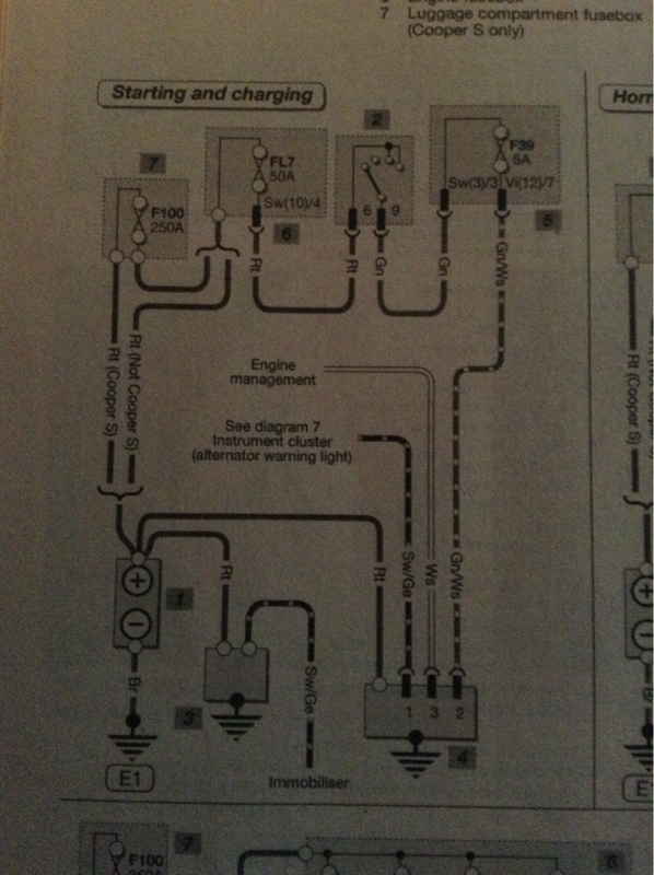
Mini Cooper S 2005 Fuse Box Block Circuit Breaker Diagram
Comfort Control Module Mini Cooper 6135 3450979 01
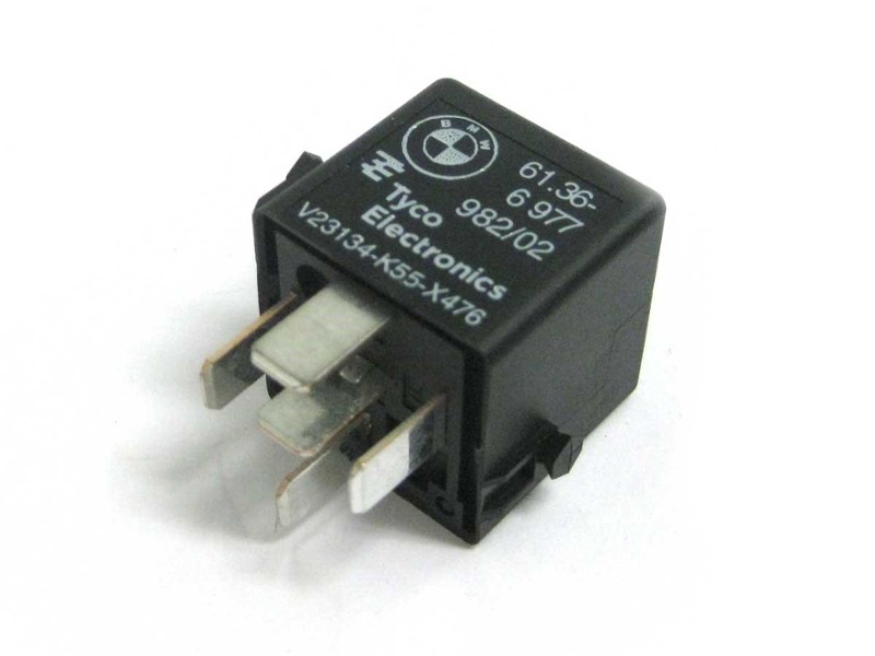
Mini Cooper Relay R1 Factory Replacement R50 R61

Ignition Switch Circuit Wiring Diagrams
F S 2006 Mini Cooper S Ready For Race Show Mbworld

1968 Mk2 Mini Cooper Woodcote Racing Classics

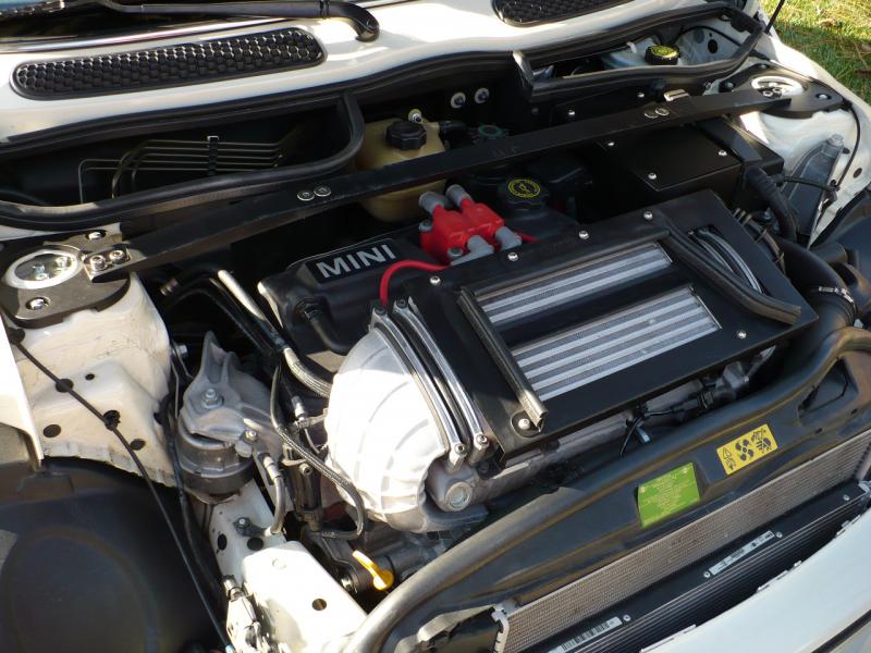
Front Bonnet Mini Cooper R53 R52 R50 Gen1 Year 2001 2006
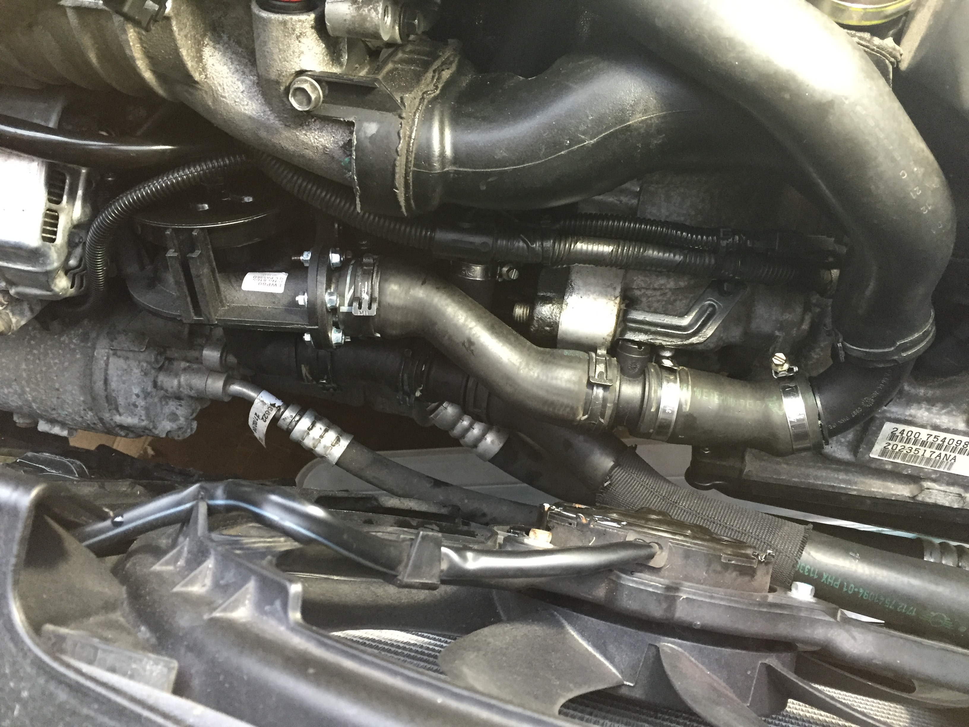
Drivetrain 2005 Mcs R53 Electric Water Pump Tpi Harmonic

Power Steering Circuit Wiring Diagrams

Solenoid Valve Circuit Wiring Diagrams

Instrument Cluster Page 4 Circuit Wiring Diagrams

 CTA Link →
sum+=1
CTA Link →
sum+=1